Unlock your potential as an architect with our exclusive eBook on Vectorworks software
With this quickstart manual you will discover the tips, tricks, and tools you need to take your designs to the next level and impress your clients. Whether you're a seasoned pro or just starting out, this eBook is a must-read for anyone serious about their craft.
When you have spent time creating elevations, plans, and sections, you can start to visualise the building. If you’re drawing with a computer, you can get the computer to create your perspectives for you. But if you’re sketching by hand, it would be good to understand how to do this manually.
Clients need to have 3D visuals to help them understand your design, they cannot read the plans, sections, and drawings. The way to help your clients is to create 3D drawings, and the first type of 3D drawing is a 1 point perspective.
What is a 1 Point Perspective?
Before the Renaissance, artists drew without perspective. Perspective drawings were a scientific breakthrough to allow art to represent the 3-D world. These days of course, we use computers to generate our perspectives based on the building we create.
One point perspective is a drawing that uses one vanishing point. A two point perspective has two vanishing points, and a three point perspective has three vanishing points.
You can think of a one point perspective is being like an elevation. An elevation shown in perspective. There are lots of prospective types that we can create (two point, or three point), but the one point perspective is easier to set up and easy to draw. At one point perspective can give clients a good idea of what they’re building will look like and it will allow them to visualise interior spaces.
Setting up a 1 Point Perspective
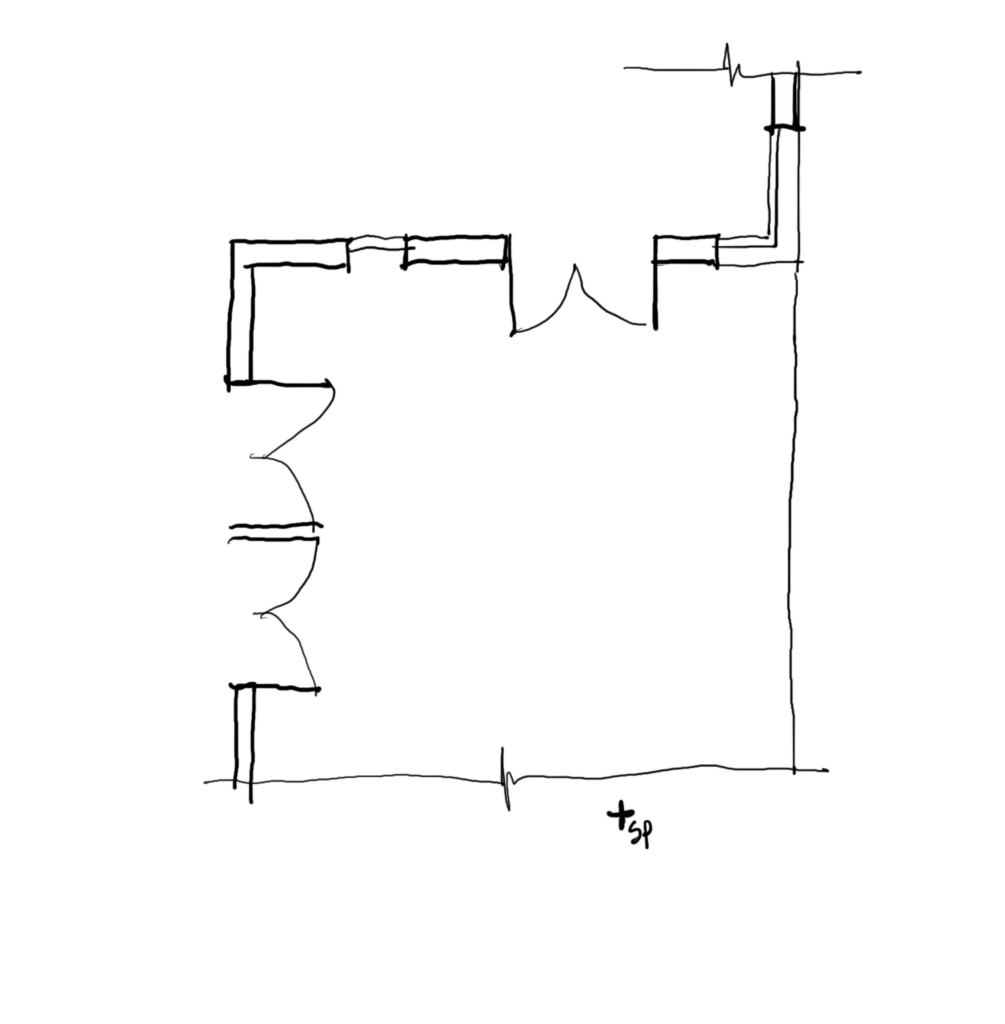
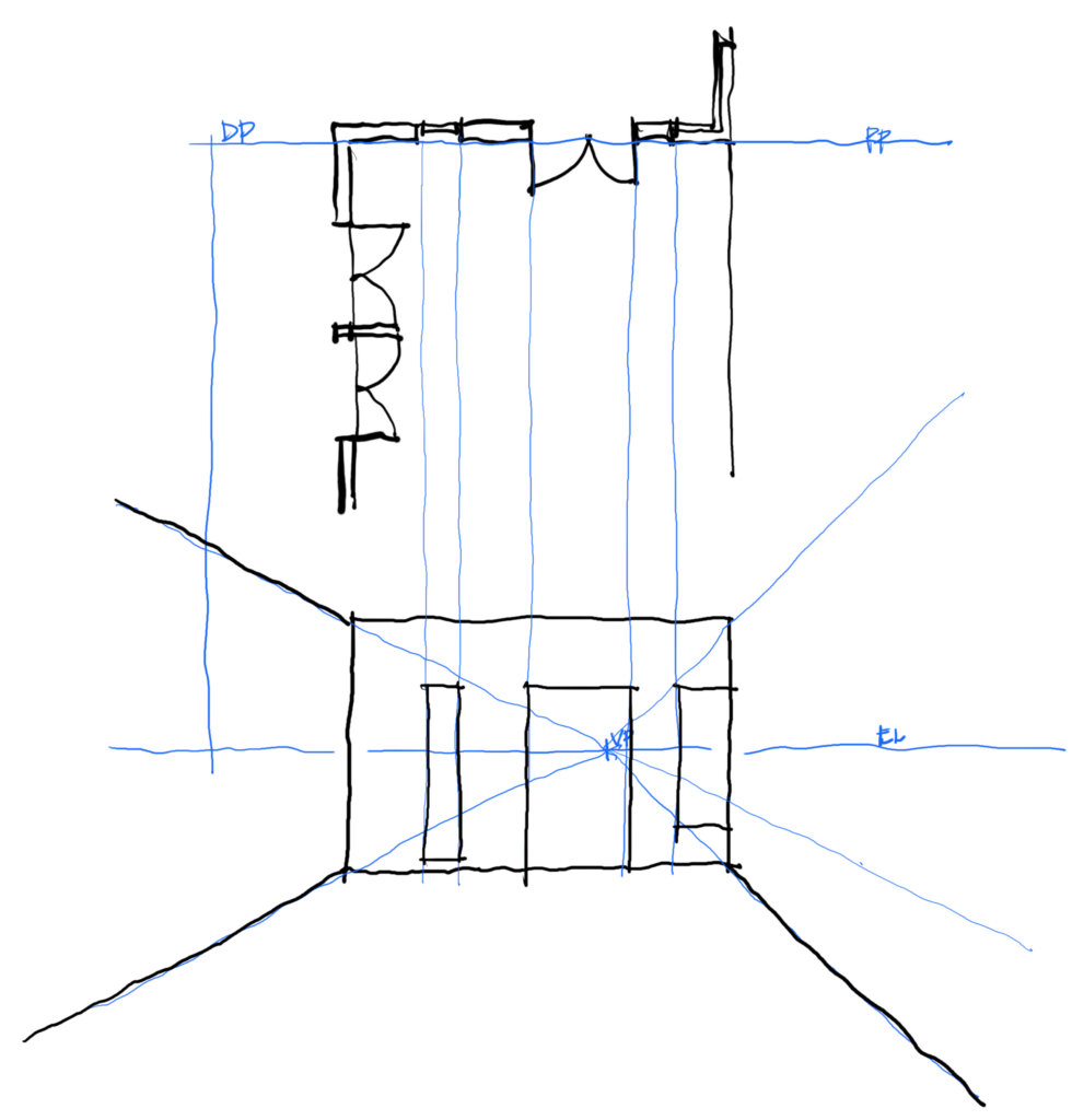
The first step and setting up a one point perspective is to place the plan above where you will be drawing your perspective.
The SP is the Station Point, this where you are standing.
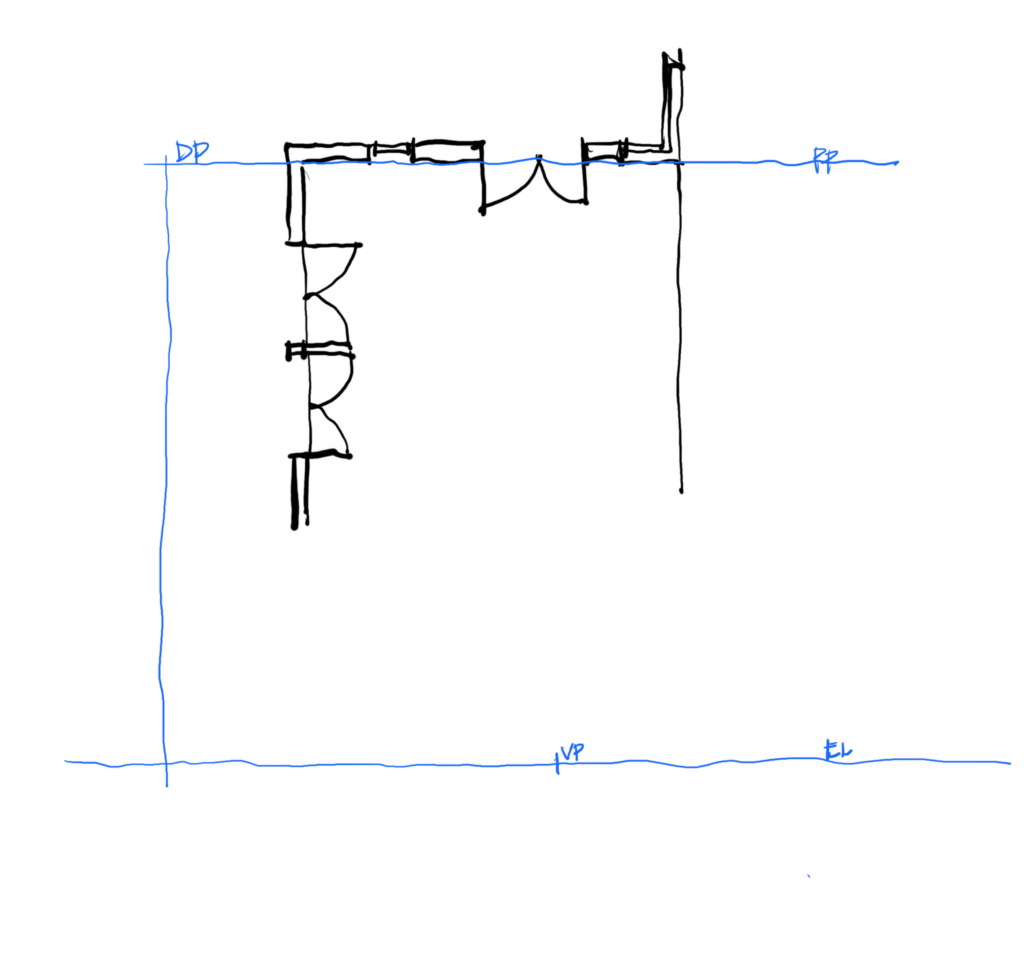
The next step is to set the Picture Plane (PP). This is the part of the plan that is to scale. You can use a true elevation of the building when the PP is aligned with the wall, so set the PP to the face of the wall.
The DP is the diagonal point, this is used to create the setting out for diagonals. The closer the DP is to the station point the deeper your perspective will look. The further away from the SP, the shallower your perspective will appear.
Draw the Eye Line (EL). This is sometimes called the Horizon Line (HL). This line sets the eye level or horizon for your drawing. Make sure you have enough room below the plan to draw your perspective.
Choose your Vanishing Point (VP). you might notice that in this perspective the VP is not in the centre of the plan. I find that slightly off centre makes a better perspective, it looks a bit more natural and dynamic.
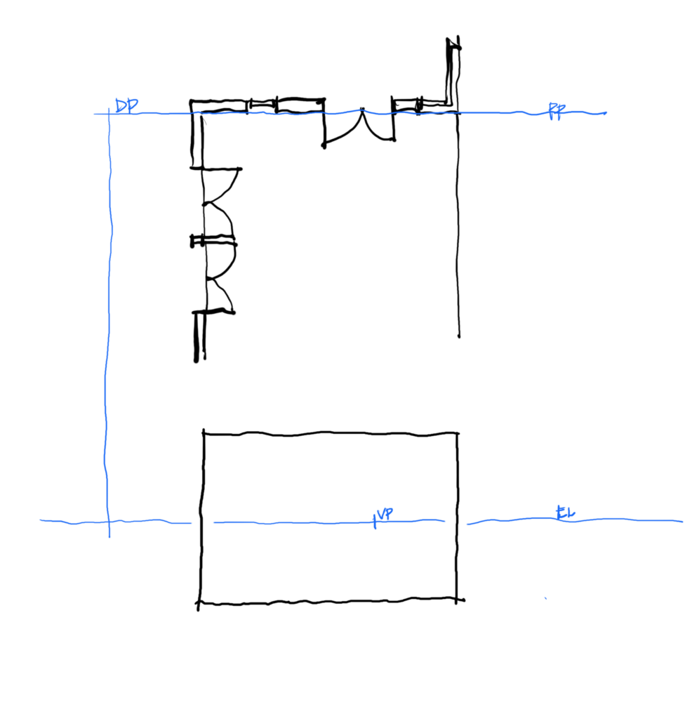
Now you can draw the elevation of the building. This can be drawn to scale if the Picture Plane aligns with the face of the building. I start with just the outline of the wall face. You might notice that in this example, the eye line is halfway up the elevation, that makes the face of the building 3m (10′) high as the eye line is usually 1.5m (5′) high.
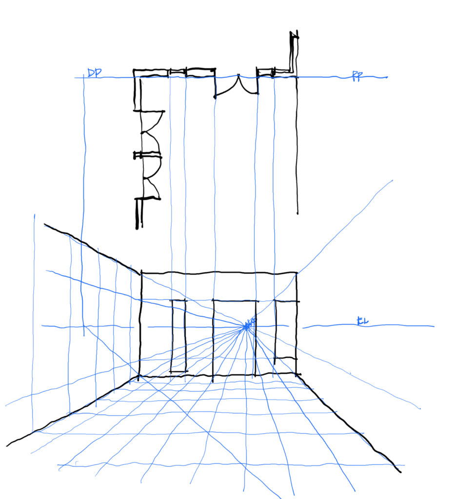
Project the lines of the wall features down to the elevation and draw the features on the elevation.
Now you can project the lines from the vanishing point through the corners of the building. I have used thin blue lines for the guide lines, then you can trace over the guide lines with a heavy pen.
The next step is to create the setting out grid and the diagonal point. Project the DP down to the EL. Draw a guide line the projected DP through the corner of the elevation.
On the elevation, create a series of 1m (3′) marks on the floor edge. Project a line from the VP though each mark. Then create a horizontal guide line at each intersection of the diagonal line.
Project these up the vertical walls as well.
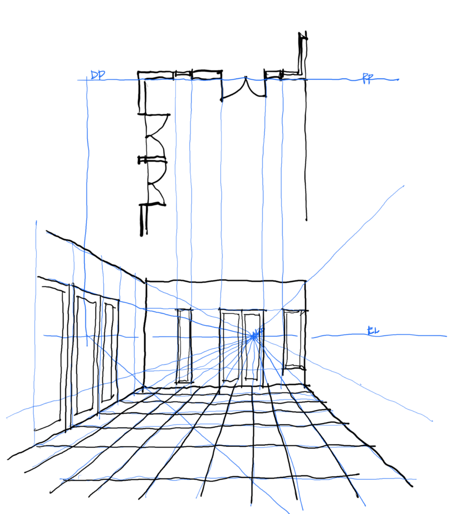
Use these guide lines to draw the wall features on the walls in perspective. Start adding heavy lines for the wall features, doors, windows, and flooring.
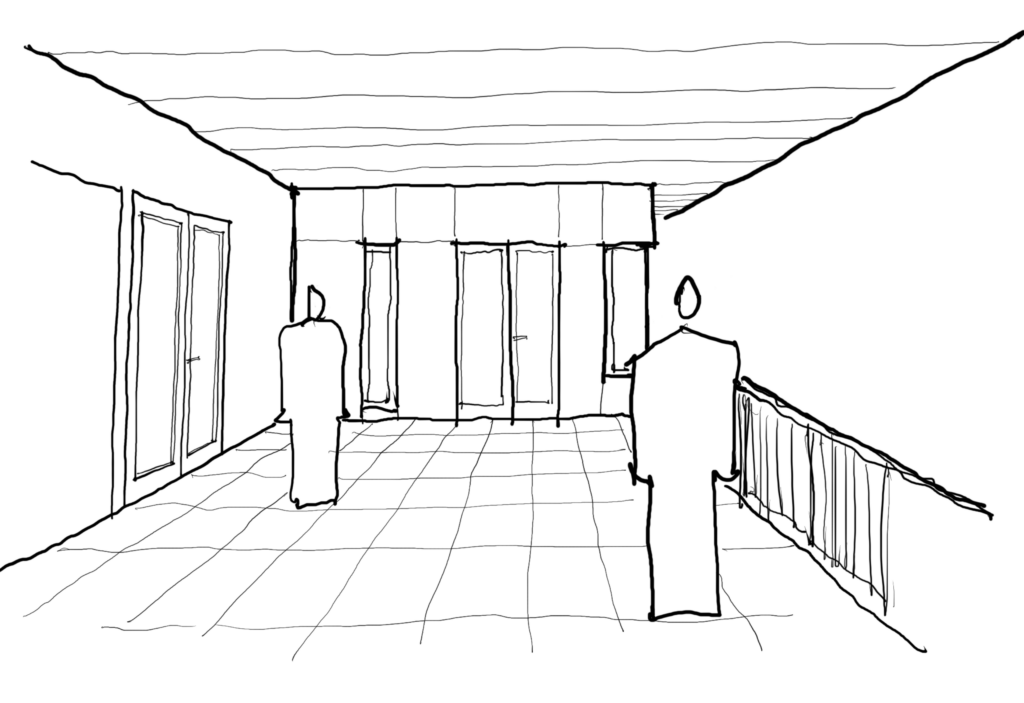
Add people
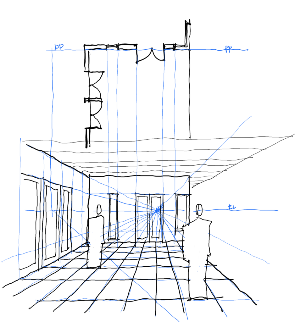
Trace over the drawing to create a clean copy of your perspective.
